Phase 1 took place between June and July 2019, when preliminary diagnostic investigations were carried out and then a rupture load test on the c3sx span, with the aim of evaluating the effective load-bearing capacity of an isostatic span under real conditions, considering the state of actual degradation and representative of a work built in the sixties and subject to routine maintenance.
Preliminary diagnostic investigations
The investigations and laboratory tests performed before carrying out the load test, complying with recent recommendations UNI/TR 11634:2016 Guidelines for structural monitoring, have had the purpose of evaluating the characteristics of the materials in order to estimate the resistant capacity of the work.
In particular, concrete cores were taken from the beams and slab, to be tested with compression and tensile tests; strands of wire from the post-tension cables to assess the yield strength, the tensile strength, and the elongation at break; samples of shear beams. Release tests were also carried out on the individual wires for the estimation of the residual prestress, samples for the evaluation of the permanent weights, a geometric relief, and finally a georadar survey with the verification of the cable layout.
These surveys were exclusively aimed at collecting the minimum and essential samples to design the load test on the C3sx span of the viaduct.
The load test
A test protocol has been defined which includes a series of loads and discharges with increasing load levels. The load unit concerned consists of a double layer of steel ballast with a size of 2,35x1,84x0,45 m and a weight of 10 t each. Each layer consists of 12 ballasts arranged according to a matrix of 3x4 elements straddling the center of the bridge, for a total of 240 t.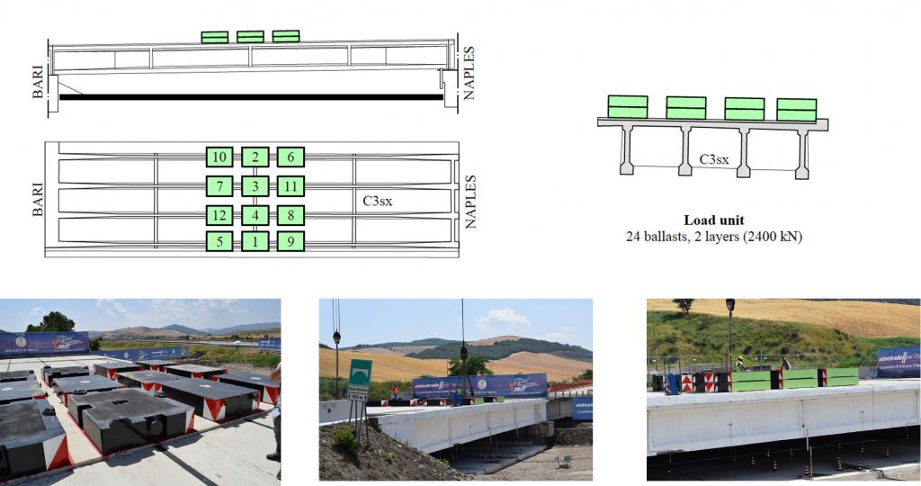
Image Test protocol
During the load test, it was decided to monitor the behavior of the viaduct, using 119 sensors, divided into eight types: wire displacement sensors, strain sensors, electronic level, temperature sensors, inclinometers, accelerometers, and acoustic emission sensors. The measurements were taken continuously throughout the test. Dynamic tests were also carried out: environmental, bridge unloading, and at the end of each loading phase. Finally, the temperature and humidity of the air and the wind speed were monitored.
The load test was then carried out in five stages, preceded by two preliminary tests on the stack and shoulder necessary to verify that the 2005 landslide had not affected the bearing capacity. The subsequent tests were carried out by loading and unloading the span with 50% of the load unit, with 100%, 200%, and 300%, and finally bringing the structure up to the maximum capacity. The last test was interrupted upon reaching the yield strength of the prestressing reinforcement, for a load value of 930 t and a lowering value of more than 300 mm.
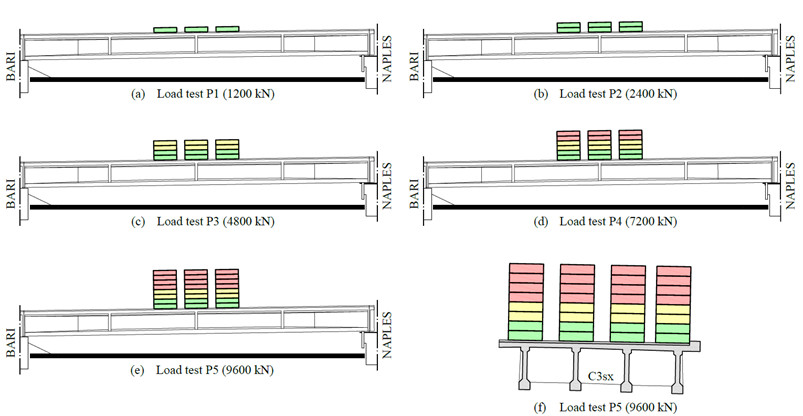
Images: Test steps; Test run
The main results obtained from the breaking load test were as follows:
The most deformed beam was found to be the T1, with a maximum centerline arrow of 314 mm at 930 t, greater than that of the T4 beam, which reaches a maximum lowering of 200 mm.
The first crack opened with a load of 330 t. The residual tension of the steel was calculated at the value inducing the crack load recorded during the test (330 t) and is σres = 952 MPa, equal to a loss of 24% with respect to the initial throw value (1,250 MPa).
It can be concluded that at 930 t the beams are completely unnerved.